Product Overview & Key Features
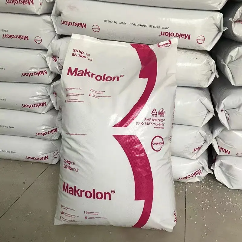
- Manufacturer: Covestro (formerly Bayer MaterialScience)
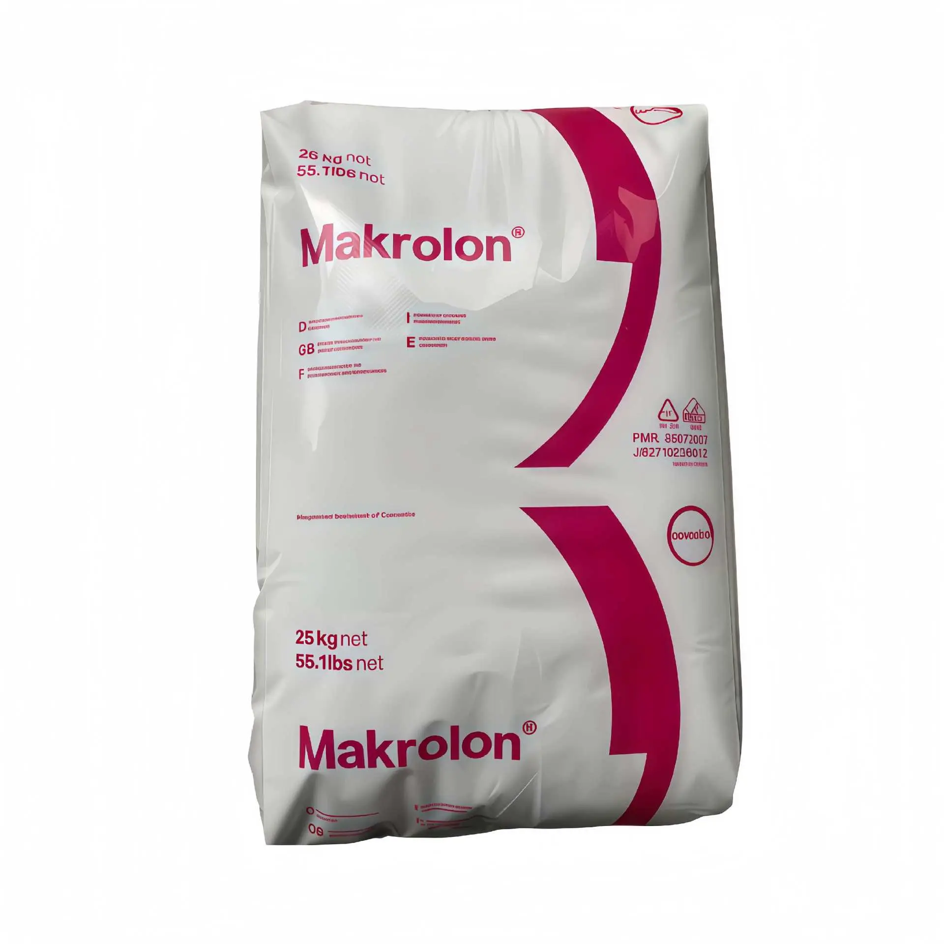
- Product series: Makrolon®
- Grade: 2807
- Material basics: Polycarbonate (PC), amorphous thermoplastic engineering plastic; general-purpose grade, medium viscosity, UV-stabilized, easy release
- Appearance: Transparent to translucent pellets
- Recommended processing: Injection molding (melt temperature 280–320 °C); higher-viscosity grades in the same series also cover extrusion
Makrolon® 2807 is a medium-viscosity grade within Covestro’s general-purpose PC (polycarbonate) range (MVR 9.0 cm³/10 min, 300 °C/1.2 kg), formulated with UV stabilization and easy-release properties. It balances transparency, toughness, heat resistance and dimensional stability, making it one of the few general-purpose materials in the engineering plastics family that delivers both optical-grade appearance and structural-grade load-bearing capability. It suits medium-wall transparent and structural parts.
Key Performance Advantages and Their Engineering Meaning
- Transparent parts can reliably replace glass and acrylic: A transmittance of 89% (1–2 mm) and haze below 0.8% (3 mm) reach optical-part standards while retaining the toughness of PC. Glass and acrylic are markedly more prone to cracking under impact, assembly stress or localized hits, which is the fundamental reason this grade suits lamp covers, viewing windows and protective lenses.
- Low-temperature toughness is a quantifiable safety margin: Unnotched specimens show no break at both -60 °C and 23 °C, and notched specimens still reach 14 kJ/m² at -30 °C. Parts used in cold chains, winter outdoor conditions or low-temperature assembly will not suffer brittle cracking — in material selection, this property sets the upper limit of part reliability more decisively than room-temperature strength.
- Long-term load-bearing depends on creep, not initial stiffness: The tensile creep modulus falls from 2200 MPa at 1 h to 1900 MPa at 1000 h, a decline of roughly 14%, which means snap fits, bosses and support structures designed on short-term modulus will deform predictably under sustained load. Combined with 0.12% equilibrium water absorption, identical expansion coefficients in both directions and a low shrinkage differential of 0.65%/0.7%, dimensional accuracy does not drift progressively in long-term service.
- The heat range covers normal electronic and lighting duty: The deflection temperature under load is 124 °C at 1.8 MPa, and the UL relative thermal index (RTI) is 125 °C for electrical, 125 °C for tensile and 115 °C for impact (1.5 mm). Parts can serve continuously at the 120 °C level and pass safety-related temperature-rise assessments without switching to another material system.
- Insulation can be designed into structural parts: A volume resistivity of 1.0E+16 Ω·cm, dielectric strength of 34 kV/mm and CTI of 250 V (test solution A) allow housings and brackets to serve as insulation at the same time, eliminating separate insulating components and assembly steps.
- Glow-wire behaviour must be judged separately from the “flammability rating”: The base resin is rated V-2 (0.75 mm) and HB (2.5 mm), yet its glow-wire flammability index (GWFI) reaches 850–930 °C with an oxygen index of 28%, giving it markedly better resistance to ignition from electrical fault heat sources than ordinary combustible plastics. Nevertheless, thin-wall parts requiring V-0 must still use a flame-retardant grade; the two cannot be interchanged.
Technical Specifications
Physical Properties
| Physical Properties | Test Value | Test Unit | Test Standard |
|---|---|---|---|
| Density (23 °C) | 1.20 | g/cm³ | ISO 1183 |
| Bulk Density | 0.66 | g/cm³ | ISO 60 |
| Melt Mass-Flow Rate (300 °C, 1.2 kg) | 10 | g/10min | ISO 1133 |
| Melt Volume-Flow Rate (300 °C, 1.2 kg) | 9.0 | cm³/10 min | ISO 1133 |
| Mold Shrinkage, Transverse | 0.60-0.80 | % | ISO 2577 |
| Mold Shrinkage, Parallel | 0.60-0.80 | % | ISO 2577 |
| Mold Shrinkage, Transverse (2 mm, 500 bar, 60x60x2mm 0, 280 °C) | 0.7 | % | ISO 294-4 |
| Mold Shrinkage, Parallel (2 mm, 500 bar, 60x60x2mm 0) | 0.65 | % | ISO 294-4 |
| Water Absorption, Saturation (23 °C) | 0.3 | % | ISO 62 |
| Water Absorption, Equilibrium (50 % RH, 23 °C) | 0.12 | % | ISO 62 |
| Ball Indentation Hardness | 115 | MPa | ISO 2039-1 |
| Water Vapor Transmission Rate (85% RH 0, 100 μm, 23 °C) | 15 | g/m²/24hr | ISO 15106-1 |
| Carbon Dioxide Permeability (25.4 μm, 23 °C) | 16900 | cm³/m²/bar/24hr | ISO 2556 |
Mechanical Properties
| Mechanical Properties | Test Value | Test Unit | Test Standard |
|---|---|---|---|
| Tensile Modulus (23 °C) | 2400 | MPa | ISO 527-2/1 |
| Tensile Stress, Yield (23 °C) | 66 | MPa | ISO 527-2/50 |
| Tensile Stress, Break (23 °C) | 70 | MPa | ISO 527-2/50 |
| Tensile Strain, Yield (23 °C) | 6.1 | % | ISO 527-2/50 |
| Tensile Strain, Break (23 °C) | 130 | % | ISO 527-2/50 |
| Nominal Tensile Strain at Break (23 °C) | > 50 | % | ISO 527-2/50 |
| Tensile Creep Modulus (1 h) | 2200 | MPa | ISO 899-1 |
| Tensile Creep Modulus (1.0e+3 h) | 1900 | MPa | ISO 899-1 |
| Flexural Modulus (2 mm/min, 23 °C) | 2400 | MPa | ISO 178 |
| Flexural Strength (2 mm/min, 23 °C) | 98 | MPa | ISO 178 |
| Flexural Strength (2 mm/min, 3.5% Strain, 23 °C) | 74 | MPa | ISO 178 |
| Flexural Strain (2 mm/min, 23 °C) | 7 | % | ISO 178 |
| Gas Permeation, Carbon Dioxide (100 μm) | 3800 | cm³/m²/bar/24hr | ISO 2556 |
| Gas Permeation, Nitrogen (25.4 μm) | 510 | cm³/m²/bar/24hr | ISO 2556 |
| Gas Permeation, Nitrogen (100 μm) | 120 | cm³/m²/bar/24hr | ISO 2556 |
| Gas Permeation, Oxygen (25.4 μm) | 2760 | cm³/m²/bar/24hr | ISO 2556 |
| Gas Permeation, Oxygen (100 μm) | 650 | cm³/m²/bar/24hr | ISO 2556 |
| Charpy Impact Strength, Notched, Complete Break (-30 °C, 3 mm) | 14 | kJ/m² | ISO 179 1eA |
| Charpy Impact Strength, Notched, Partial Break (23 °C, 3 mm) | 75 | kJ/m² | ISO 179 1eA |
| Charpy Impact Strength, Unnotched (-60 °C) | No Break | — | ISO 179 1eU |
| Charpy Impact Strength, Unnotched (-30 °C) | No Break | — | ISO 179 1eU |
| Charpy Impact Strength, Unnotched (23 °C) | No Break | — | ISO 179 1eU |
| Izod Impact Strength, Notched, Complete Break (-30 °C, 3 mm) | 15 | kJ/m² | ISO 180/1A |
| Izod Impact Strength, Notched, Partial Break (23 °C, 3 mm) | 70 | kJ/m² | ISO 180/1A |
| Instrumented Impact Test, Total Energy (-30 °C) | 65 | J | ISO 6603-2 |
| Instrumented Impact Test, Total Energy (23 °C) | 60.0 | J | ISO 6603-2 |
| Instrumented Impact Test, Peak Force (-30 °C) | 6300 | N | ISO 6603-2 |
| Instrumented Impact Test, Peak Force (23 °C) | 5400 | N | ISO 6603-2 |
Thermal Properties
| Thermal Properties | Test Value | Test Unit | Test Standard |
|---|---|---|---|
| Heat Deflection Temperature, Unannealed (0.45 MPa) | 136 | °C | ISO 75-2/B |
| Heat Deflection Temperature, Unannealed (1.8 MPa) | 124 | °C | ISO 75-2/A |
| Glass Transition Temperature (Tg) (10 °C, min 0) | 144 | °C | ISO 11357-2 |
| Vicat Softening Temperature | 143 | °C | ISO 306/B50 |
| Vicat Softening Temperature | 145 | °C | ISO 306/B120 |
| Ball Pressure Test (135 °C) | Pass | — | IEC 60695-10-2 |
| Coefficient of Linear Thermal Expansion (CTE), Parallel (23-55 °C) | 6.5E-5 | cm/cm/°C | ISO 11359-2 |
| Coefficient of Linear Thermal Expansion (CTE), Transverse (23-55 °C) | 6.5E-5 | cm/cm/°C | ISO 11359-2 |
| Thermal Conductivity, Normal to Surface (23 °C) | 0.2 | W/m-K | ISO 8302 |
| Relative Thermal Index (RTI), Electrical (1.5 mm) | 125 | °C | UL 746 |
| Relative Thermal Index (RTI), Impact (1.5 mm) | 115 | °C | UL 746 |
| Relative Thermal Index (RTI), Tensile (1.5 mm) | 125 | °C | UL 746 |
| Flammability Rating (2.5 mm) | HB | — | UL 94 |
| Flammability Rating (0.75 mm) | V-2 | — | UL 94 |
| Glow-Wire Flammability Index (GWFI) (0.75 mm) | 850 | °C | IEC 60695-2-12 |
| Glow-Wire Flammability Index (GWFI) (1.5 mm) | 850 | °C | IEC 60695-2-12 |
| Glow-Wire Flammability Index (GWFI) (3 mm) | 930 | °C | IEC 60695-2-12 |
| Glow-Wire Ignition Temperature (GWIT) (0.75 mm) | 875 | °C | IEC 60695-2-13 |
| Glow-Wire Ignition Temperature (GWIT) (1.5 mm) | 875 | °C | IEC 60695-2-13 |
| Glow-Wire Ignition Temperature (GWIT) (1.5 mm) | 750 | °C | EDF HN60 E.02 |
| Glow-Wire Ignition Temperature (GWIT) (3 mm) | 875 | °C | IEC 60695-2-13 |
| Glow-Wire Ignition Temperature (GWIT) (3 mm) | 750 | °C | EDF HN60 E.02 |
| Oxygen Index, Procedure A | 28 | % | ISO 4589-2 |
| Small Burner Test, Methods K and F (2 mm) | K1·F1 | — | DIN 53438-1 |
| Burning Rate (> 1 mm) | passed | — | ISO 3795 |
| Flash Ignition Temperature | 480 | °C | ASTM D1929 |
| Needle Flame Test, Method F (1.5 mm) | 1.00 | min | IEC 60695-11-5 |
| Needle Flame Test, Method K (1.5 mm) | 0.1 | min | IEC 60695-11-5 |
| Needle Flame Test, Method F (2 mm) | 1.00 | min | IEC 60695-11-5 |
| Needle Flame Test, Method K (2 mm) | 0.1 | min | IEC 60695-11-5 |
| Needle Flame Test, Method K (3 mm) | 0.2 | min | IEC 60695-11-5 |
| Needle Flame Test, Method F (3 mm) | 2.0 | min | IEC 60695-11-5 |
| Self-Ignition Temperature | 550 | °C | ASTM D1929 |
Electrical Properties
| Electrical Properties | Test Value | Test Unit | Test Standard |
|---|---|---|---|
| Surface Resistivity | 1.0e+16 | Ohms | IEC 60093 |
| Volume Resistivity (23 °C) | 1.0E+16 | ohms·cm | IEC 60093 |
| Dielectric Strength (23 °C, 1 mm) | 34 | kV/mm | IEC 60243-1 |
| Dielectric Constant (100 Hz, 23 °C) | 3.1 | — | IEC 60250 |
| Dielectric Constant (1.0e+6 Hz, 23 °C) | 3 | — | IEC 60250 |
| Dissipation Factor (100 Hz, 23 °C) | 5.0E-4 | — | IEC 60250 |
| Dissipation Factor (1.0e+6 Hz, 23 °C) | 9.0E-3 | — | IEC 60250 |
| Comparative Tracking Index (CTI), Test Solution A | 250 | V | IEC 60112 |
| Comparative Tracking Index (CTI), Test Solution B | 125 | V | IEC 60112 |
Chemical Properties
| Chemical Properties | Test Value | Test Unit | Test Standard |
|---|---|---|---|
| Electrolytical Corrosion (23 °C) | A1 | — | IEC 60426 |
Optical Properties
| Optical Properties | Test Value | Test Unit | Test Standard |
|---|---|---|---|
| Refractive Index | 1.586 | — | ISO 489 |
| Transmittance (1 mm) | 89 | % | ISO 13468-2 |
| Transmittance (2 mm) | 89 | % | ISO 13468-2 |
| Transmittance (3 mm) | 88 | % | ISO 13468-2 |
| Transmittance (4 mm) | 87 | % | ISO 13468-2 |
| Haze (3 mm) | < 0.8 | % | ISO 14782 |
Notice: The technical specifications for Covestro Makrolon® 2807 provided herein are compiled from data published by Covestro or certified third-party testing laboratories. While prepared with professional diligence, these values serve as reference guidelines rather than absolute performance guarantees. Because molding and processing conditions vary significantly across operational environments, we recommend performing trial runs with Makrolon® 2807 under your actual manufacturing conditions prior to final material selection and mass production.
Applications & Processing Guidelines
Recommended Applications and End-Use Parts
- Lighting and optical parts: Lamp covers, lenses and light guides. The optical data meet imaging and light-transmission requirements, and the 124 °C heat deflection temperature covers the normal temperature rise of LED luminaires, so parts resist deformation or yellowing in long-term service.
- Electrical and electronic: Terminal blocks, switch panels, circuit-breaker housings and transparent instrument covers. The insulation properties are sufficient for housings to double as insulating parts; the flammability rating must be checked against the actual wall thickness of the finished part, and thin-wall parts requiring V-0 should switch to a flame-retardant grade. The selection logic is set out in plastics for electrical connectors and relays.
- Automotive and transportation: Transparent instrument-cluster covers, interior lighting lenses and sensor housings. The low-temperature impact data support reliable service in cold regions.
- Home appliances and consumer products: Transparent windows for coffee machines and kettles, microwave oven viewing windows and control panels, using heat resistance, insulation and transparency together.
- Safety protection and industrial windows: Safety spectacle lenses, face shields, instrument viewing windows and machine guards, relying mainly on impact resistance and dimensional stability.
- Precision structural parts: Medium-wall transparent structural parts and long-term load-bearing components, with stiffness checked against the creep data (see Section 4).
Processing Essentials
- Drying: the precondition that determines whether parts become brittle. PC chains contain ester groups, and in the presence of water at melt temperature they hydrolyse, so a drop in molecular weight ultimately shows up as embrittlement. Before injection molding, dry the pellets in a dehumidifying dryer at 120 °C to a residual moisture content of no more than 0.02% (no more than 0.01% for extrusion). Insufficient drying appears first in the appearance (silver streaks, bubbles) and then in impact strength. Dried pellets reabsorb moisture, so the amount fed at one time should not be excessive.
- Temperature window: melt 280–320 °C, mold ≥80 °C. A melt temperature that is too low causes incomplete filling and higher internal stress, while one that is too high accelerates thermal degradation and yellowing; holding the mold at 80–120 °C gives low internal stress, good surface quality and stable release. This grade is easy to release, so an external mold release agent is normally unnecessary. Optical parts in particular require a uniform mold temperature, otherwise optical distortion occurs.
- Gates and shrinkage: control anisotropy at the mold design stage. Shrinkage is 0.65% in the flow direction and 0.7% in the transverse direction, a small but non-negligible difference. A medium-viscosity melt is sensitive to shear, so a larger gate cross-section and a tapered runner are recommended to reduce shear heat and orientation stress.
- Annealing: relieving internal stress in thick-wall and high-precision parts. For thick-walled parts or components with very high dimensional-stability requirements, annealing below the glass transition temperature followed by slow cooling releases molded-in stress and reduces the risk of later cracking under chemical media or load; the temperature and duration depend on wall thickness and part geometry.
Grade Comparison & Selection Guide
Comparison Across Comparable Grades
The grades compared below are general-purpose and flame-retardant grades from Covestro’s Makrolon® series, with MVR measured at 300 °C/1.2 kg.
| Grade | Viscosity Class | MVR | UV-Stabilized | Flammability Rating (as published) | Performance Characteristics |
|---|---|---|---|---|---|
| 2807 (this grade) | Medium | 9.0 cm³/10 min | Yes | Not flame-retardant specific (per this page’s datasheet: V-2/0.75 mm, HB/2.5 mm) | Best balance of transparency, toughness, heat resistance and flow; general-purpose transparent parts and medium-wall structural parts |
| 2805 | Medium | 9.0 cm³/10 min | No | Not flame-retardant specific | Same flow as 2807 but without UV stabilization; suitable for indoor parts with no light exposure |
| 2407 | Low | 19 cm³/10 min | Yes | — | Higher flow; suitable for thin walls, long flow paths and fast cycles |
| 3107 | High | 6.0 cm³/10 min | Yes | — | High melt strength; suitable for thick-walled parts and extruded profiles |
| Makrolon® 6557 | Medium | 10 cm³/10 min | Yes | UL 94 V-0 (3.0 mm) | Flame-retardant grade for electrical parts subject to thin-wall flammability requirements |
Where this grade sits in the matrix: The general-purpose range is divided by viscosity into low (MVR 19–34), medium (9.0–12) and high (6.0) bands, and 2807 sits in the middle band, making it the most balanced option across all four properties. Compared with 2805 it adds UV stabilization; compared with flame-retardant grades such as 6557 it contains no flame-retardant system. Its role is therefore to cover general-purpose transparent and structural requirements, leaving thin-wall V-0 compliance needs to the flame-retardant grades.
Selection Guidance for Engineers
| Selection Factor | Recommendation |
|---|---|
| Wall thickness and flow length | Wall thickness <1.5 mm or long flow paths → low-viscosity grade (2407); wall thickness >4 mm or extruded profiles → high-viscosity grade (3107); medium wall thickness with normal flow → 2807 |
| Flammability compliance | Where V-0 is required and the part has thin walls → a flame-retardant grade must be used, with the minimum wall thickness checked against the thickness certified on its UL Yellow Card; 2807 applies only to V-2/HB scenarios |
| Light exposure | Outdoor use or long-term light exposure → choose a UV-stabilized grade (2807/2407/3107/6557); for indoor parts with no light exposure, 2805 may be considered |
| Long-term loading | Check against the creep modulus (2200 MPa at 1 h → 1900 MPa at 1000 h); do not apply the short-term tensile modulus of 2400 MPa directly |
| Mold gate design | Use a larger gate cross-section with a tapered runner, together with a uniform mold temperature of ≥80 °C, to reduce shear heat and orientation-induced internal stress |
Frequently Asked Questions (FAQs)
Q1: Is drying mandatory before processing, and how should the drying conditions be set?
A: It is mandatory. PC chains contain ester groups, and even trace moisture triggers hydrolysis at melt temperature. The direct consequence is a reduction in molecular weight and embrittlement of the part; it shows up first as silver streaks and bubbles, after which impact strength falls irreversibly. The recommended drying temperature is 120 °C, and residual moisture before injection molding should be kept below 0.02% (below 0.01% for extrusion). A dehumidifying dryer should be used, with the hopper kept sealed.
Q2: How do I choose between 2807 and other grades in the same series?
A: Two criteria are enough, and both are set out in Section 4: medium-wall parts with normal flow use 2807 or 2805, thin-wall long-flow parts use 2407, and thick-walled or extruded parts use 3107; as soon as thin-wall V-0 compliance is required, a flame-retardant grade such as 6557 must be used. The one easily overlooked difference is weatherability — 2805 contains no UV stabilization and suits indoor parts with no light exposure only.
Q3: Why does the flammability rating in the datasheet vary with wall thickness, and what do HB and V-2 mean?
A: UL 94 ratings are tied directly to specimen thickness, and the same material can receive different ratings at different thicknesses — this grade is V-2 at 0.75 mm and HB at 2.5 mm, so discussing “whether it is flame retardant” without specifying wall thickness is meaningless. HB is the lowest rating for horizontal burning; V-2 requires the flame to self-extinguish within 30 seconds in vertical burning, while allowing drips that may ignite cotton. When selecting a grade, first establish the minimum wall thickness of the finished part, then check the Yellow Card data for that thickness and request third-party reports for that thickness where necessary.
Q4: For transparent parts, should I choose PC or PMMA (acrylic)?
A: The differences centre on toughness, heat resistance and surface hardness. This grade already matches acrylic in transmittance, but its impact resistance is significantly higher and its heat deflection temperature of 124 °C (1.8 MPa) is far above acrylic, making it suitable for parts exposed to drop risk, high-temperature environments or impact loads; acrylic’s advantages lie in better surface hardness and scratch resistance and lower material cost. Where a part is purely for appearance display with no impact or high-temperature requirements, a PMMA (acrylic) material can be evaluated; where transparency and structural load-bearing must both be met, PC is the priority choice.